Low-Power-Pulse-Triggered-Flip-Flop-Design-Based-on-a-Signal-Feed-Through-Scheme
Our Price
₹4,500.00
10000 in stock
Support
Ready to Ship
Description
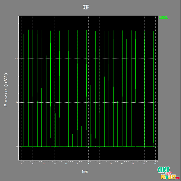
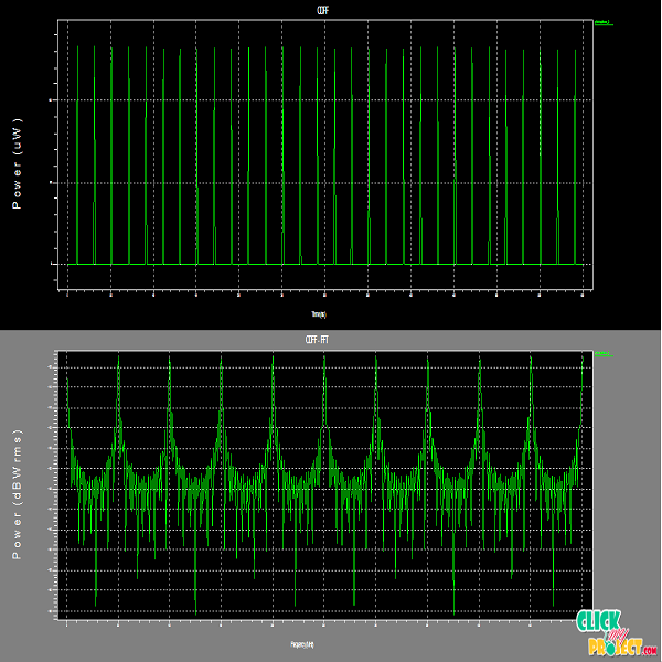
Flip-flops and latches are used as data storage elements. Such data storage can be used for storage of state, and such a circuit is described as sequential logic. Flip-flops can be either simple (transparent or opaque) or clocked (synchronous or edge-triggered). The simple ones are commonly called latches. The word latch is mainly used for storage elements, while clocked devices are described as flip-flops. A latch is level-sensitive, whereas a flip-flop is edge-sensitive. That is, when a latch is enabled it becomes transparent, while a flip flop’s output only changes on a single type (positive going or negative going) of clock edge. a flip-flop or latch is a circuit that has two stable states and can be used to store state information. A flip-flop is a bistable multi vibrator. When used in a finite-state machine, the output and next state depend not only on its current input, but also on its current state (and hence, previous inputs). It can also be used for counting of pulses, and for synchronizing variably-timed input signals to some reference timing signal. The circuit can be made to change state by signals applied to one or more control inputs and will have one or two outputs. Simple flip-flops can be built around a pair of cross-coupled inverting elements: vacuum tubes, bipolar transistors, field effect transistors, inverters, and inverting logic gates have all been used in practical circuits. In this proposed implementation design is consists four types of flip flops such as ep-DCO, CDFF, MHLFF and the proposed design in tanner eda design tool.
Tags: 2016, Domain > VLSI Projects

